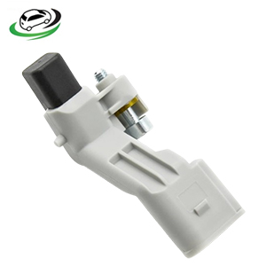
Get Crankshaft Position Sensor Audi A3 2.0L l4 / VW Golf 2.0L/CC Sedan 2.0L/Golf R 2.0L/Tiguan 2.0L/GTI 2.0L/Eos 2.0L 03C906433A
The crankshaft position sensor is a crucial component in modern internal combustion engines. It plays a vital role in engine management systems, ensuring optimal performance, fuel efficiency, and emissions control. This guide will delve into the function, construction, types, symptoms of failure, diagnosis, and replacement of the crankshaft position sensor.
What is a Crankshaft Position Sensor?
The crankshaft position sensor is an electronic device that monitors the position and rotational speed of the crankshaft. It provides this information to the engine control unit (ECU), which uses the data to manage various aspects of engine operation, including ignition timing and fuel injection. The sensor ensures that the engine’s pistons fire at the correct time, which is essential for efficient combustion and smooth operation.
Functions of the Crankshaft Position Sensor
The crankshaft position sensor performs several critical functions in the engine:
- Monitoring Crankshaft Position: The primary function of the crankshaft position sensor is to detect the position of the crankshaft relative to the engine’s pistons. It monitors the rotation of the crankshaft and determines the position of each piston, which is essential for synchronizing the engine’s operation.
- Providing Data for Ignition Timing: The sensor’s data is used by the ECU to determine the exact moment to ignite the fuel-air mixture in each cylinder. Accurate ignition timing is crucial for efficient combustion, engine performance, and fuel efficiency.
- Controlling Fuel Injection: The crankshaft position sensor also plays a role in controlling fuel injection timing. By knowing the exact position of the crankshaft, the ECU can precisely control when fuel is injected into each cylinder, optimizing the combustion process.
- Enabling Misfire Detection: The sensor helps the ECU detect engine misfires by monitoring the crankshaft’s rotational speed. If a cylinder misfires, the sensor detects a deviation in the crankshaft’s speed, allowing the ECU to take corrective action.
- Supporting Variable Valve Timing (VVT): In engines with variable valve timing, the crankshaft position sensor provides the necessary data to adjust the timing of the intake and exhaust valves, optimizing engine performance and efficiency.
Construction of the Crankshaft Position Sensor
The crankshaft position sensor is typically composed of several key components:
- Sensor Housing: The sensor housing is usually made of durable plastic or metal, designed to protect the internal components from heat, vibration, and contaminants.
- Magnet or Coil: Inside the sensor, there is a magnet or coil that generates a magnetic field. This magnetic field interacts with the crankshaft’s reluctor ring (or tone wheel), producing an electrical signal as the crankshaft rotates.
- Hall Effect or Inductive Sensor Element: The sensor element is responsible for detecting changes in the magnetic field as the reluctor ring passes by. There are two main types of sensor elements: Hall effect sensors and inductive sensors.
- Hall Effect Sensors: These sensors use a semiconductor material that produces a voltage when exposed to a magnetic field. They generate a digital signal (on/off) corresponding to the position of the crankshaft.
- Inductive Sensors: Inductive sensors generate an analog signal (AC voltage) based on the speed and position of the crankshaft. The signal’s frequency and amplitude change with the crankshaft’s rotation.
- Connector and Wiring: The sensor is connected to the ECU via a wiring harness. The connector provides a secure connection between the sensor and the ECU, allowing the transmission of data.
Types of Crankshaft Position Sensors
Crankshaft position sensors can be categorized into several types based on their design and sensing method:
- Hall Effect Sensors: These sensors use the Hall effect principle to generate a digital signal based on the position of the crankshaft. They are known for their accuracy and reliability and are commonly used in modern engines.
- Inductive Sensors: Inductive sensors generate an analog signal based on the rotational speed and position of the crankshaft. They are durable and resistant to harsh conditions, making them suitable for use in various engine types.
- Optical Sensors: Optical crankshaft position sensors use a light source and a photodetector to monitor the position of the crankshaft. As the crankshaft rotates, it interrupts the light beam, allowing the sensor to detect its position. Optical sensors are less common and are typically used in specialized applications.
- Magnetoresistive Sensors: These sensors use magnetoresistive materials that change their resistance based on the magnetic field produced by the crankshaft. They offer high precision and are often used in high-performance engines.
Symptoms of a Failing Crankshaft Position Sensor
A failing crankshaft position sensor can lead to various engine performance issues. Common symptoms of a faulty sensor include:
- Engine Stalling: A failing crankshaft position sensor can cause the engine to stall intermittently or fail to start altogether. This occurs because the ECU cannot accurately control ignition timing and fuel injection without data from the sensor.
- Poor Acceleration: A faulty sensor may cause the engine to lose power or hesitate during acceleration. This is due to incorrect ignition timing or fuel injection, leading to inefficient combustion.
- Check Engine Light: A malfunctioning crankshaft position sensor often triggers the check engine light. The ECU stores a diagnostic trouble code (DTC) related to the sensor, which can be read with an OBD-II scanner.
- Rough Idling: A failing sensor can cause the engine to idle roughly or experience fluctuations in RPM. This is due to incorrect data being sent to the ECU, leading to improper engine management.
- Misfires and Backfiring: If the sensor is sending erratic signals, it can cause the engine to misfire or backfire. This occurs because the ECU is unable to synchronize the ignition and fuel injection properly.
- No Start Condition: In severe cases, a completely failed crankshaft position sensor can prevent the engine from starting. Without a signal from the sensor, the ECU cannot initiate the ignition and fuel injection processes.
Diagnosing a Faulty Crankshaft Position Sensor
Diagnosing a faulty crankshaft position sensor typically involves the following steps:
- Check for Diagnostic Trouble Codes (DTCs): Use an OBD-II scanner to check for any stored DTCs related to the crankshaft position sensor. Common codes include P0335 (Crankshaft Position Sensor Circuit Malfunction) and P0336 (Crankshaft Position Sensor Range/Performance).
- Inspect the Sensor and Wiring: Visually inspect the sensor and its wiring for any signs of damage, such as frayed wires, loose connectors, or physical damage to the sensor housing.
- Test the Sensor with a Multimeter: Use a multimeter to test the sensor’s resistance, voltage, or signal output, depending on the type of sensor. Compare the readings to the manufacturer’s specifications to determine if the sensor is functioning correctly.
- Check the Reluctor Ring: Inspect the crankshaft reluctor ring for any signs of damage or wear. A damaged reluctor ring can cause the sensor to produce erratic signals.
- Perform a Sensor Waveform Analysis: For more advanced diagnostics, a technician can use an oscilloscope to analyze the sensor’s waveform. This allows for a detailed examination of the sensor’s signal output during engine operation.
Replacing the Crankshaft Position Sensor
If a crankshaft position sensor is determined to be faulty, it should be replaced promptly to restore proper engine operation. The replacement process generally involves the following steps:
- Locate the Sensor: The crankshaft position sensor is typically located near the crankshaft, often at the front or side of the engine. Consult the vehicle’s service manual for the exact location.
- Disconnect the Battery: Before replacing the sensor, disconnect the vehicle’s battery to prevent any accidental short circuits.
- Remove the Sensor Connector: Carefully disconnect the wiring harness from the sensor. Be gentle to avoid damaging the connector or wiring.
- Remove the Old Sensor: Use the appropriate tools to remove the bolts or fasteners securing the sensor in place. Once the fasteners are removed, carefully extract the sensor from its mounting location.
- Install the New Sensor: Install the new crankshaft position sensor in the reverse order of removal. Ensure that the sensor is properly aligned and securely fastened.
- Reconnect the Wiring Harness: Reconnect the wiring harness to the new sensor, making sure the connector is fully seated.
- Reconnect the Battery: Reconnect the vehicle’s battery and start the engine. Monitor the engine’s operation to ensure that the new sensor is functioning correctly.
Choosing the Right Crankshaft Position Sensor
When selecting a replacement crankshaft position sensor, consider the following factors:
- OEM vs. Aftermarket: OEM (Original Equipment Manufacturer) sensors are designed to meet the exact specifications of your vehicle and are generally more reliable. Aftermarket sensors can vary in quality, so choose a reputable brand if opting for an aftermarket part.
- Compatibility: Ensure that the sensor is compatible with your vehicle’s make, model, and engine configuration. Verify the part number and specifications before making a purchase.
- Quality and Durability: Look for sensors that are built to withstand the harsh conditions of the engine environment, including heat, vibration, and exposure to oil and other contaminants.
- Follow us on Facebook for more parts.


