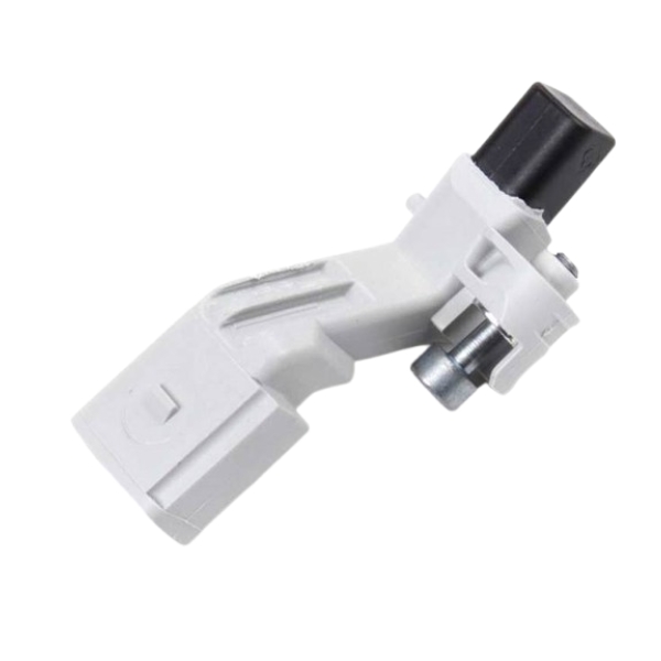
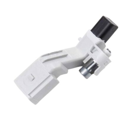
Get Volkswagen Jetta 1.9L Diesel Crankshaft Position Sensor 036906433E in Kenya
The crankshaft position sensor (CKP sensor) is a crucial component in modern internal combustion engines, playing an essential role in the engine management system. It provides critical data about the crankshaft’s position and rotational speed to the engine control unit (ECU), enabling precise control over ignition timing, fuel injection, and other vital engine functions. This ensures optimal performance, fuel efficiency, and emission control. In this comprehensive guide, we will explore the function, construction, types, importance, common issues, diagnostics, and maintenance of the crankshaft position sensor.
Function of the Crankshaft Position Sensor
Primary Role
- Position Detection: The primary function of the crankshaft position sensor is to monitor the exact position of the crankshaft as it rotates within the engine. The sensor detects the position of the crankshaft relative to the pistons, which is essential for determining the timing of the engine’s operations.
- RPM Monitoring: In addition to position detection, the crankshaft position sensor measures the rotational speed (revolutions per minute, or RPM) of the crankshaft. This information is critical for the ECU to regulate engine functions accurately.
Interaction with the ECU
- Ignition Timing: The crankshaft position sensor provides real-time data to the ECU, allowing it to determine the precise moment to trigger the spark plugs for ignition. Proper ignition timing is essential for efficient combustion and engine performance.
- Fuel Injection Timing: The sensor also helps the ECU determine the optimal timing for fuel injection into the combustion chambers. Accurate fuel injection timing is crucial for maintaining the correct air-fuel mixture and ensuring efficient combustion.
- Synchronization with Camshaft Position Sensor: The crankshaft position sensor often works in tandem with the camshaft position sensor. While the crankshaft sensor monitors the position and speed of the crankshaft, the camshaft sensor tracks the position of the camshaft. Together, they provide the ECU with the information needed to control valve timing and synchronize the engine’s overall operation.
Additional Functions
- Engine Start-up: During engine start-up, the crankshaft position sensor provides the initial data that the ECU needs to begin the ignition and fuel injection processes. Without accurate input from the CKP sensor, the engine may fail to start or run inefficiently.
- Misfire Detection: By continuously monitoring the crankshaft’s position and speed, the sensor can help detect engine misfires. The ECU can use this information to adjust ignition timing or fuel delivery to prevent further misfires and protect the engine.
Construction of the Crankshaft Position Sensor
Key Components
- Sensor Housing: The housing encases the sensor’s internal components and protects them from harsh environmental conditions such as heat, moisture, and vibration. The housing is typically made of durable plastic or metal.
- Sensing Element: The sensing element is the core part of the sensor that detects the position and speed of the crankshaft. Depending on the type of sensor, this element could be a magnet, Hall effect sensor, or inductive coil.
- Magnet (for Hall Effect Sensors): In Hall effect sensors, a magnet generates a magnetic field that interacts with the crankshaft’s target wheel. The sensor detects changes in the magnetic field as the crankshaft rotates, allowing it to determine the position and speed of the crankshaft.
- Target Wheel (Reluctor Ring): The crankshaft position sensor works in conjunction with a target wheel, also known as a reluctor ring, which is attached to the crankshaft. The target wheel typically has teeth or notches that pass by the sensor, creating a signal that corresponds to the crankshaft’s position and speed.
- Connector: The sensor has an electrical connector that links it to the vehicle’s wiring harness and ECU. This connector transmits the sensor’s data to the ECU for processing.
Types of Crankshaft Position Sensors
- Magnetic Inductive Sensors:
- Principle: These sensors operate based on electromagnetic induction. As the reluctor wheel’s teeth pass by the sensor’s magnetic coil, they generate a fluctuating magnetic field, inducing a voltage signal that corresponds to the crankshaft’s position and speed.
- Characteristics: Inductive sensors are simple, durable, and capable of operating in harsh environments. However, they typically produce a lower-resolution signal compared to Hall effect sensors.
- Hall Effect Sensors:
- Principle: Hall effect sensors use a magnetic field generated by a permanent magnet within the sensor. As the target wheel’s teeth pass through this magnetic field, the sensor detects changes in the magnetic flux, producing a digital signal that indicates the crankshaft’s position and speed.
- Characteristics: Hall effect sensors are more precise than inductive sensors and can generate high-resolution digital signals. They are commonly used in modern engines due to their accuracy and reliability.
- Optical Sensors:
- Principle: Optical sensors use a light-emitting diode (LED) and a photodetector to measure the crankshaft’s position. As the crankshaft rotates, a slotted disk attached to it interrupts the light beam, and the sensor detects these interruptions to determine the crankshaft’s position and speed.
- Characteristics: Optical sensors are less common in automotive applications due to their sensitivity to dust, dirt, and oil contamination, which can interfere with the light beam.
Importance of the Crankshaft Position Sensor
Engine Performance
- Precise Timing Control: The crankshaft position sensor is vital for precise control of ignition and fuel injection timing, ensuring that the engine operates efficiently and delivers optimal performance.
- Improved Fuel Efficiency: By enabling accurate timing of the combustion process, the CKP sensor helps maximize fuel efficiency, reducing fuel consumption and emissions.
- Smoother Engine Operation: Proper synchronization of the engine’s components, facilitated by the CKP sensor, leads to smoother operation, reducing engine noise, vibrations, and harshness (NVH).
Emission Control
- Reduced Emissions: Accurate timing of fuel injection and ignition, as controlled by the CKP sensor, ensures complete combustion, minimizing the production of harmful emissions such as carbon monoxide (CO), hydrocarbons (HC), and nitrogen oxides (NOx).
- Compliance with Regulations: Vehicles equipped with a properly functioning CKP sensor are more likely to meet stringent emissions regulations, helping reduce the environmental impact of automotive engines.
Diagnostic Tool
- Fault Detection: The crankshaft position sensor plays a critical role in the vehicle’s onboard diagnostic system (OBD). If the sensor detects a problem, it can trigger a diagnostic trouble code (DTC) and illuminate the check engine light, alerting the driver to a potential issue.
- Misfire Monitoring: The sensor’s ability to detect engine misfires is essential for protecting the engine from damage and ensuring that the vehicle operates safely and efficiently.
Common Issues with Crankshaft Position Sensors
Symptoms of a Faulty CKP Sensor
- Engine Stalling: A failing CKP sensor can cause the engine to stall unexpectedly, especially at low speeds or when idling. This is due to the ECU receiving incorrect or no data about the crankshaft’s position.
- No Start Condition: If the sensor fails completely, the engine may not start because the ECU cannot determine the crankshaft’s position and therefore cannot initiate the ignition and fuel injection processes.
- Misfires and Rough Idling: A malfunctioning CKP sensor can cause erratic ignition timing, leading to engine misfires, rough idling, and poor acceleration.
- Reduced Power and Performance: Without accurate data from the CKP sensor, the ECU may enter a “limp mode” or default to a less efficient timing strategy, resulting in reduced engine power and performance.
- Check Engine Light: A faulty CKP sensor often triggers the check engine light, accompanied by a diagnostic trouble code related to the sensor.
Causes of CKP Sensor Failure
- Heat Damage: The sensor is typically located near the crankshaft, where it is exposed to high temperatures. Prolonged exposure to heat can cause the sensor to fail over time.
- Electrical Problems: Corroded or damaged wiring, poor connections, or a faulty sensor connector can disrupt the sensor’s signal to the ECU, leading to performance issues.
- Physical Damage: The sensor or its target wheel can be damaged by debris, improper installation, or mechanical issues within the engine.
- Magnetic Interference: In the case of Hall effect sensors, strong magnetic fields from nearby components or external sources can interfere with the sensor’s operation.
Diagnostics and Maintenance
Diagnosing a Faulty CKP Sensor
- OBD-II Scan: Use an OBD-II scanner to check for diagnostic trouble codes (DTCs) related to the crankshaft position sensor. Common codes include P0335 (Crankshaft Position Sensor “A” Circuit) and P0336 (Crankshaft Position Sensor “A” Circuit Range/Performance).
- Visual Inspection: Inspect the sensor and its wiring for signs of damage, corrosion, or loose connections. Check the target wheel (reluctor ring) for damage or misalignment.
- Signal Testing: Use a multimeter or oscilloscope to test the sensor’s output signal. An inductive sensor should produce an AC voltage signal as the crankshaft rotates, while a Hall effect sensor should produce a square wave digital signal.
- Resistance Check: For inductive sensors, check the resistance across the sensor terminals using a multimeter. Compare the reading to the manufacturer’s specifications to determine if the sensor is within the correct range.
Maintenance Tips
- Regular Inspections: Periodically inspect the CKP sensor, its wiring, and connectors for signs of wear, damage, or corrosion, especially during routine engine maintenance.
- Proper Installation: Ensure the sensor is installed correctly, with the appropriate gap between the sensor and the target wheel, as specified by the manufacturer.
- Protect from Heat: If possible, shield the sensor from excessive heat exposure by ensuring proper engine cooling and avoiding aftermarket modifications that may increase engine bay temperatures.
- Prompt Replacement: Replace the CKP sensor at the first sign of failure or according to the manufacturer’s recommended service intervals to prevent engine performance issues.
Replacement Procedure
- Disconnect Battery: Always disconnect the battery before working on the sensor to avoid electrical shocks and accidental engine starts.
- Access the Sensor: Locate the sensor, typically found near the crankshaft pulley or flywheel, and remove any components obstructing access, such as engine covers or belts.
- Remove the Sensor: Disconnect the sensor’s electrical connector, then unbolt and carefully remove the sensor from its mounting location.
- Install the New Sensor: Position the new sensor in place, ensuring the correct alignment with the target wheel. Tighten the mounting bolt to the specified torque and reconnect the electrical connector.
- Test the Engine: Reconnect the battery, start the engine, and check for smooth operation and the absence of any error codes or check engine lights.
Follow us on Facebook for more parts.


